Building description & plans:
The building was built up in 1910. Its carcass facade is very characteristic for Stuttgart. The object has five floors and attic with eleven apartments. The basement consists of two floors. The north and west facades of the object were in the course of time additionally rendered, therefore the building lost its authenticity. The last rebuilding happend in 1994; the attic was rebuilt and provided with 10cm of additional thermal insulation. The enclosure wall is brickwork with very different thickness from 25 cm to 51 cm. The ceiling of the basement floor is from reinforced concrete and the remaining ceilings are made from timber beam structure. The windows are old wood double windows. Some of them have window-blinds. In front of the east facade there is a sun lounge of a very bad quality. The object has a central heating system and domestic hot water preparing. In most of the rooms the corners are mouldy, hence lowering the living standard. For the existing object was elaborated an energy certificate containing also a modernization option. The results were checked using computer simulation program Capsol and completed with possibility of the application of electronically controlled sun shades and mechanical ventilation.


Plans:
 "first floor")
 "typical floor")
 "attic")
 "section")
 "west facade")
 "east facade")
The energy certificate of the building:
The building energy rating is based on "a steady state energy balance, but taking account of internal and external temperature variations and, through an utilisation factor, of the dynamic effect of internal and solar gains. It is a simplified calculation method for assessment of the heat use and energy needed for space heating of a residential building, or a part of it, which will be referred to as "the building". This method includes the calculations of: the heat losses of the building when heated to constant temperature; the annual heat needed to maintain the specified set-point temperatures in the building; the annual energy required by the heating system of the building for space heating." (EN 832 Thermal performance of buildings - Calculation of energy use for heating - Residential buildings)
On the basis of the simplified calculation method is:
| The annual heat demand: | 170,96 [kWh/(m2.a)] |
| The total energy demand: | 251,83 [kWh/(m2.a)] |
| The annual primary energy demand: | 279,55 [kWh/(m2.a)] |
| The mean thermal transmittance of the building: | 1,72 [W/(m2.K)] |
| The CO2 Emissions: | 62,9 [kg/m2] |
| The energy class of the building: | E - Average building |

Thermal transmittance of the building construction before / after modernization:
| Building construction | U-Value [W/(m2.K)] | |
| Facade (mean) | 2,18 | 0,29 |
| Windows | 2,70 | 1,01 |
| Roof | 0,46 | 0,30 |
| Basement ceiling | 1,33 | 0,28 |
| Ceiling to the stairs | 0,70 | 0,70 |
The modernization variants were designed with following measures:
- Thermal insulation of the facade with a 10cm EPS-insulation boards
- Exchange of the windows with U-value: 1,01 [W/(m2.K)]
- Thermal insulation of the basement ceiling with a 8 cm mineral insulation boards
- Additional thermal insulation of the roof with a 6 cm mineral insulation boards
- Removal of the glazing veranda and its replacement by a new similar, though thermally disconnected, construction
- Exchange of the furnace with a new condensing boiler with utilization of solar energy for hot water preparation in the range of 20 per cent
After the modernization would be on the basis of simplified calculation method:
| The annual heat demand: | 54,29 [kWh/(m2.a)] |
| The total energy demand: | 86,75 [kWh/(m2.a)] |
| The annual primary energy demand: | 97,47 [kWh/(m2.a)] |
| The mean thermal transmittance of the building: | 0,45 [W/(m2.K)] |
| The CO2 emmissions | 22 [kg/m2] |
| The energy class of the building: | B - Good energy efficiency |

The energy certificate of the building:


Computer simulation:
The energy efficiency of the building was checked with the program Capsol and indoor comfort was also calibrated with Capsol. Capsol is a computer program to calculate multizonal steady-state and dynamic heat transfer, including one dimensional heat conduction, convection, view factor based infrared radiation, multizonal ventilation and solar radiation. During the dynamic calculation a system of energy balance equations is built and solved each calculation time step, using a finite difference method. The steady state calculation can be used to estimate the required heating and cooling loads. Capsol consists of four computer programs: input module, calculation module, functions editor module and wall type editor module. All these programs work seamlessly together - in the course of problem definition, calculation and reporting of the results. More information about the program Capsol is available at www.physibel.be.

Not only the heated zones are shown, but also the unheated zones. Heated zone were divided into three parts:
1. First floor
2. Attic
3. Single floors (between first floor and attic)
Unheated zones were defined:
1. Basement floor
2. Stairs
The results of the energy certificate after checking:
Existing state - annual heat demand: 235,1 [kWh/(m2.a)]
After the modernization - annual heat demand: 66,5 [kWh/(m2.a)]

An automatic sun protection was designed for the improvement of the indoor comfort in summer. The next chart representes the curve of the indoor temperature in a control point after using this sun protection.

More studies with a 8cm, 10cm, 12cm, 14cm, 16cm and 18cm mineral board were performed in order to optimalize the thickness of the thermal insulation of the facade. The next chart shows the relation between the mean U-Value, annual heat energy demand and the thermal insulation thickness.

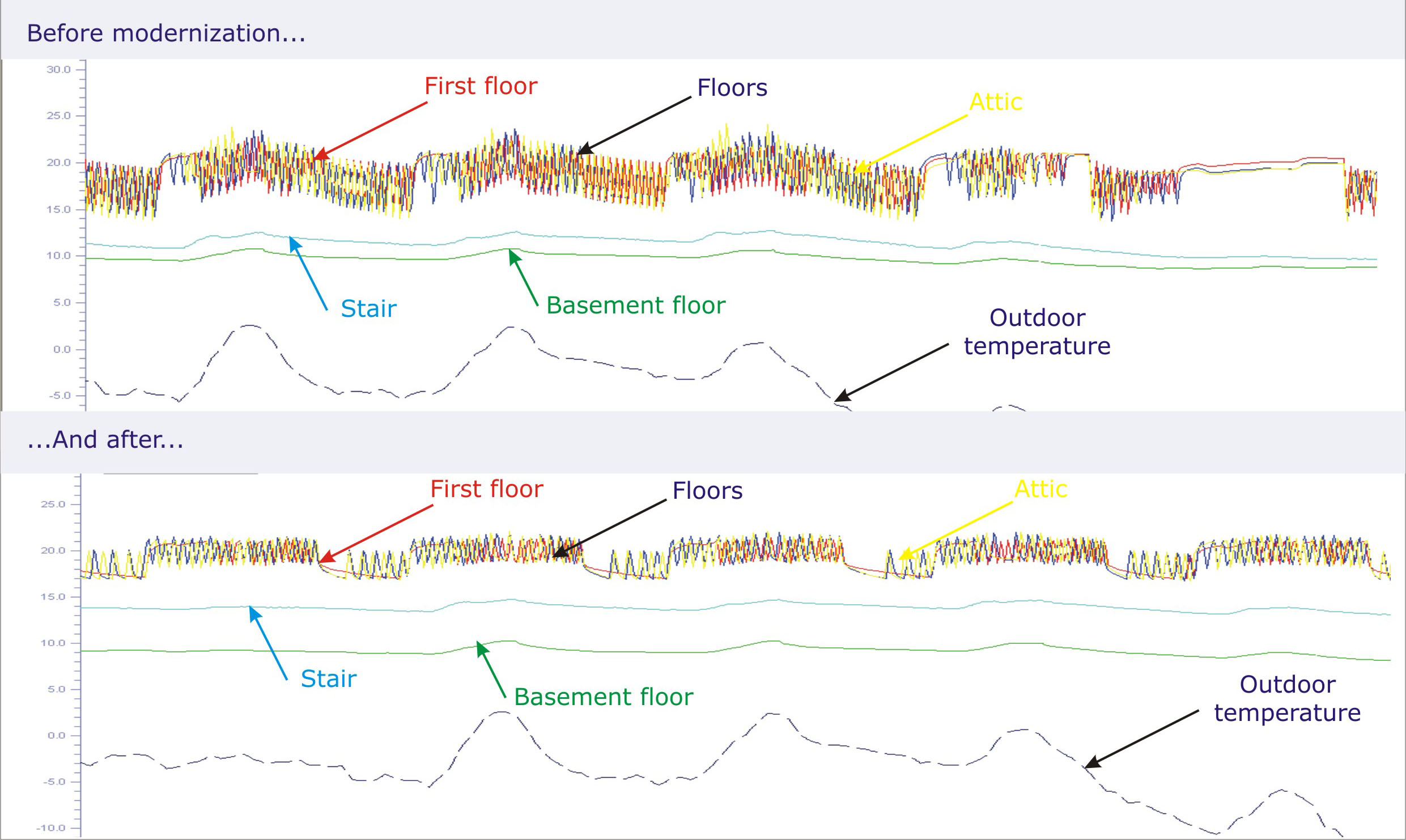
The following charts show the Capsol simulation results for the given heated and unheated zones for the climate of Stuttgart during the reference year. They represent the indoor temperature, the heating control and the sunscreen control:
1.Comparison of the indoor temperature in heated and unheated zones in winter (actual state and state after the modernization)
2. Comparison of the indoor temperature in heated and unheated zones in summer (actual state, state after the modernization and state after the modernization and application of the sun screen)
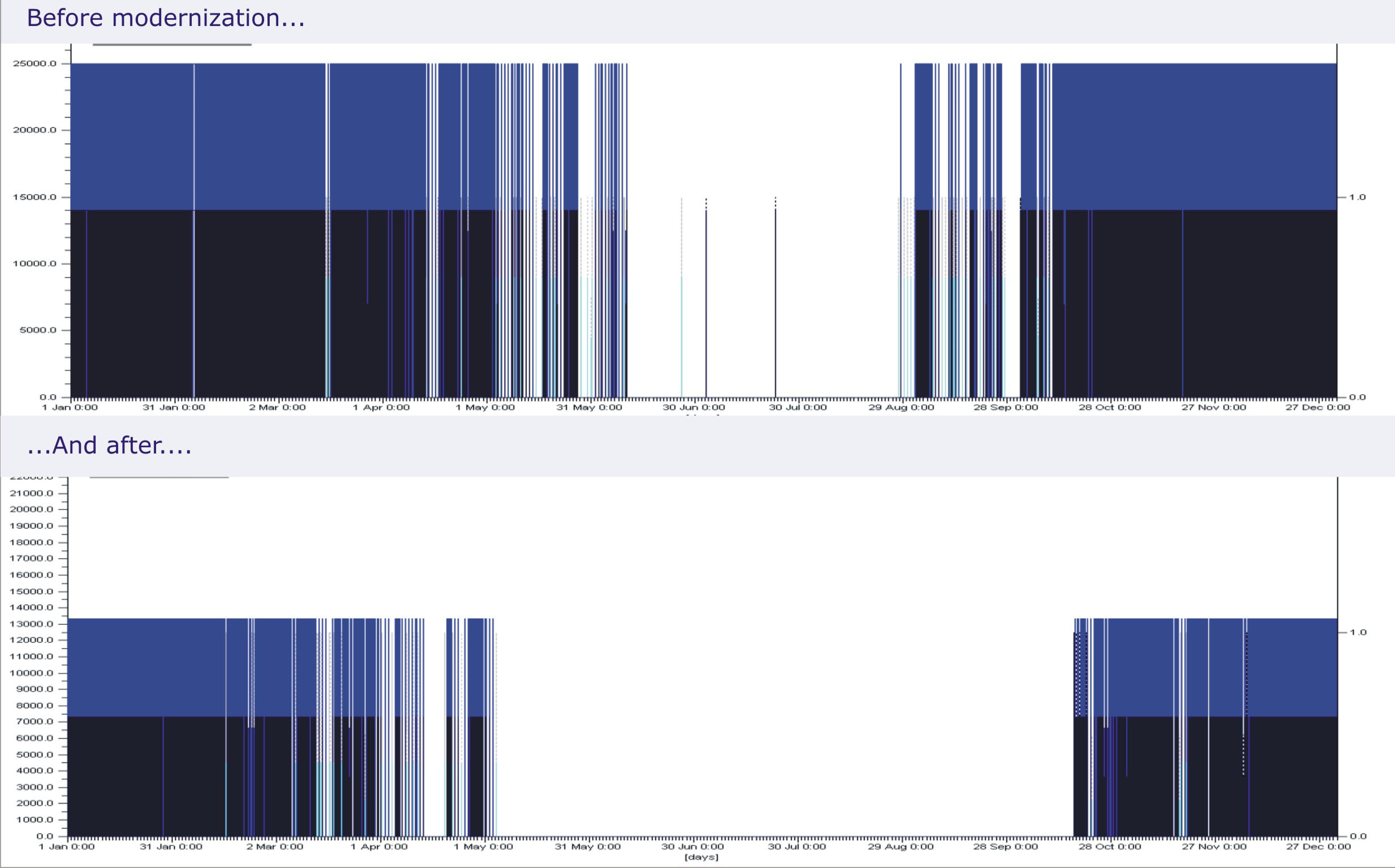
3. The heating season in existing state and in case of proposed modernization
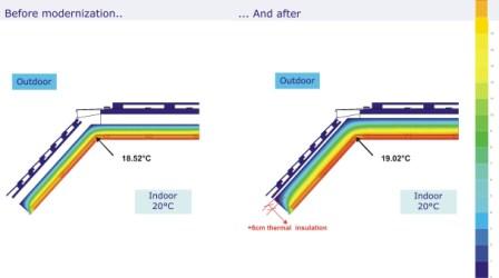
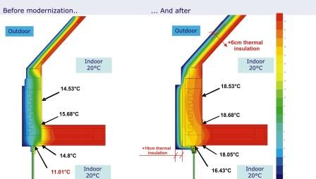
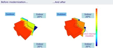
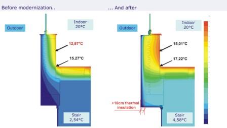
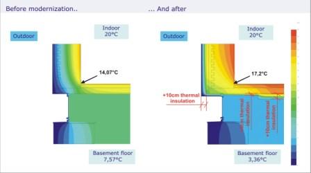
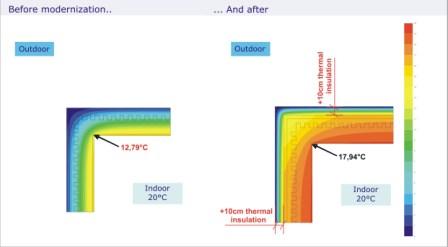
Thermal Bridges:
The design of the details of this building-study (before modernization) adverts to the critical thermal bridges and corners of the building. The condition of the minimum internal surface temperature is not fulfilled. The covering of the walls with a sufficient thickness of thermal insulation eliminates the probability of moulds occuring on the internal surface. The critical building-details were checked with program Bisco and Trisco.
Bisco is a thermal analysis program for steady state heat transfer in two-dimensional objects consisting of different materials and submitted to different boundary conditions. The geometry is defined by a coloured picture in bitmap format. Bisco requires data input for the association of the bitmap colours with the physical properties of materials and boundary conditions. Bisco calculates automatically a triangulation for the materials colours, whereas the system nodes are located in the triangle vertices. Then it calculates the temperatures in the nodes, from which all heat flows can be derived.
Trisco is a thermal analysis program for steady state heat transfer in three-dimensional rectangular objects consisting of different materials and submitted to different boundary conditions. The geometry is described with a list of rectangular blocks, the vertices of which lie on grid points of a rectangular grid. Materials and surface boundary conditions with different thermal properties are identified using separate colours. Each geometry block is part of either a material or a surface boundary condition region, and has a reference to one of these colours. Node boundary conditions with fixed temperature or power are possible, and can be placed in grid point location. Also border face boundary conditional in the interface between two colour regions with fixed temperature or heat flux, or material boundary conditions with fixed temperature or heat power density are possible. After input of geometry and thermal properties a system of linear equations is calculated based on the energy balance technique, and solved using a fast iterative method. Possible non-linear behaviour is solved by use of different cycles of adjusted linear system.
More information about the programs Bisco and Trisco can be found at the web site www.physibel.be.
The following pictures show the critical details of the building before and after the proposed modernization.


Detail "A"
Detail "B"
Detail "C"
Detail "C" (3D)
Detail "D"
Detail "E"
Detail "E" (3D)
Detail "F"
Detail "G"
Detail "G" (3D)
Detail "H"
Detail "I"